CONTENTS
1.2 Objectives of the Location Plan
2....... Indicative Works Areas and Boundaries of the Project
3....... Locations of key environmental mitigation measures
Annexes
Annex A Overall BPPS Pipeline Route
Annex B Indicative Works Areas for the BPPS Pipeline
Annex C Vertical and Horizontal Alignments of the BPPS Pipeline
Annex D Indicative Works Areas for the GRS at BPPS
List of Tables
Table 3.1 Locations of Key Environmental Mitigation Measures
List of Figures
Figure 1.1 Indicative Location of Key Project Components
To support the increased use of natural gas in Hong Kong from 2020 onwards, Castle Peak Power Company Limited (CAPCO) and The Hongkong Electric Company, Limited (HK Electric) have identified that the development of an offshore liquefied natural gas (LNG) receiving terminal in Hong Kong using Floating Storage and Regasification Unit (FSRU) technology (‘the Hong Kong Offshore LNG Terminal Project’) presents a viable additional gas supply option that will provide energy security through access to competitive gas supplies from world markets. The Hong Kong Offshore LNG Terminal Project will involve the construction and operation of an offshore LNG import facility to be located in the southern waters of Hong Kong, a double berth jetty, and subsea pipelines that connect to the gas receiving stations (GRS) at the Black Point Power Station (BPPS) and the Lamma Power Station (LPS).
The Environmental Impact Assessment (EIA) Report for the Hong Kong Offshore LNG Terminal Project was submitted to the Environmental Protection Department (EPD) of the Hong Kong Special Administrative Region Government in May 2018. The EIA Report (EIAO Register No. AEIAR-218/2018) was approved by EPD and the associated Environmental Permit (EP) (EP-558/2018) was issued in October 2018. An application for Further Environmental Permits (FEP) were made on 24 December 2019 to demarcate the works between the different parties. The following FEPs were issued on 17 January 2020 and the EP under EP-558/2018 was surrendered on 5 March 2020:
§ the double berth jetty at LNG Terminal under the Hong Kong LNG Terminal Limited, joint venture between CAPCO and HK Electric (FEP-01/558/2018/A) ([1]);
§ the subsea gas pipeline for the BPPS and the associated GRS in the BPPS under CAPCO (FEP-03/558/2018); and
§ the subsea gas pipeline for the LPS and the associated GRS in the LPS under HK Electric (FEP-02/558/2018/A) ([2]).
The location plan for the works associated with the subsea gas pipeline for BPPS and the associated GRS in BPPS (‘the Project’) is provided in Figure 1.1.
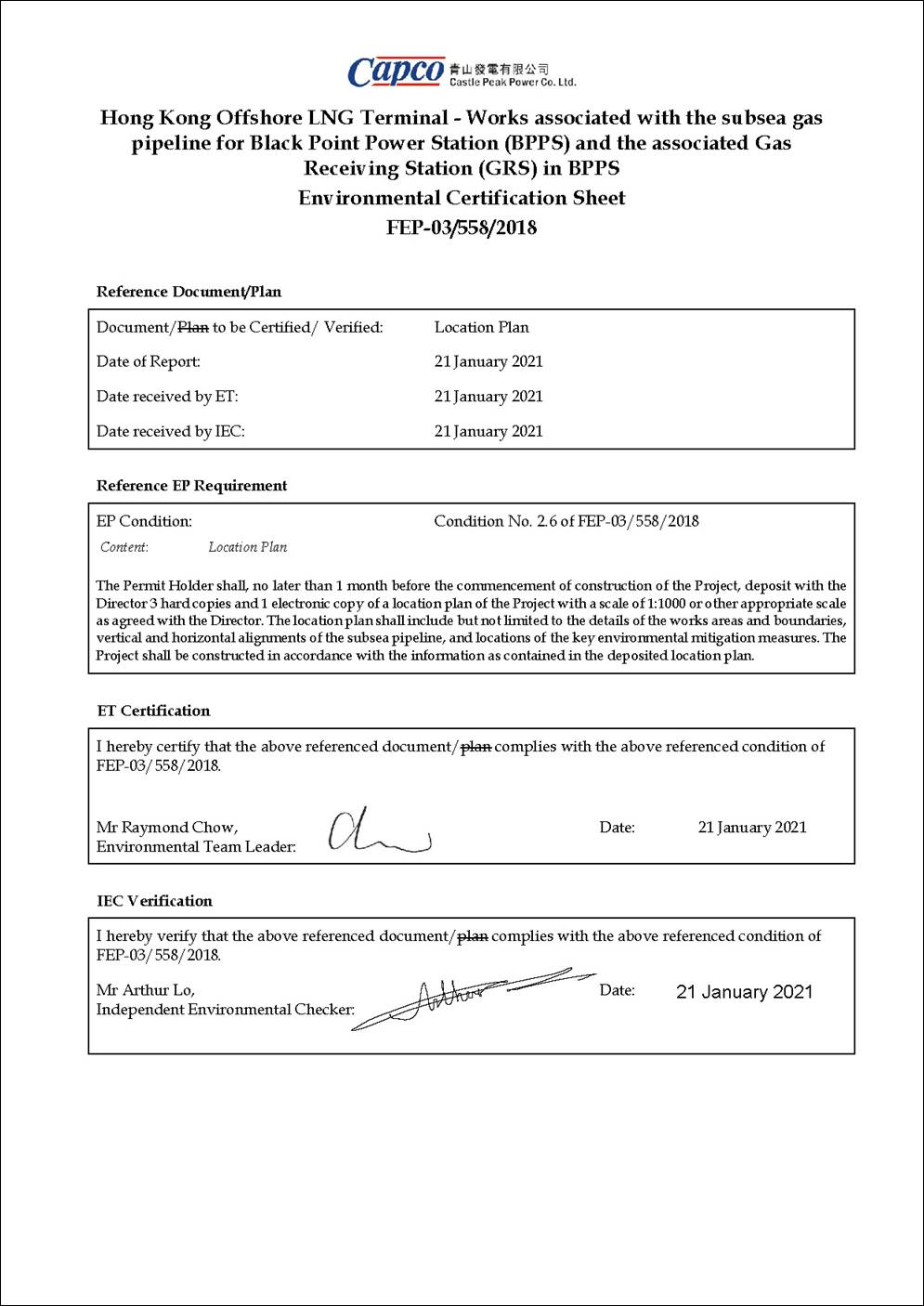
This Location Plan for the Project has been prepared in accordance with Condition 2.6 of the Further Environmental Permit FEP-03/558/2018.
|
FEP No. FEP-03/558/2018, Condition 2.6: “The Permit Holder shall, no later than 1 month before the commencement of construction of the Project, deposit with the Director 3 hard copies and 1 electronic copy of a location plan of the Project with a scale of 1:1000 or other appropriate scale as agreed with the Director. The location plan shall include but not limited to the details of the works areas and boundaries, vertical and horizontal alignments of the subsea pipeline, and locations of the key environmental mitigation measures. The Project shall be constructed in accordance with the information as contained in the deposited location plan.” |
The key objectives of this Location Plan are to:
§ include the details of the works areas and boundaries, vertical and horizontal alignments of the subsea pipeline; and
§ include locations of the key environmental mitigation measures.
The Location Plan will be reviewed and updated as appropriate,
throughout the course of the construction works to confirm that it remains
current with the latest detailed information and works practice.
The Project contains the following key facilities:
§ A subsea gas pipeline connecting the LNG Terminal with the BPPS (‘the BPPS Pipeline’); and
§ A GRS located entirely within the BPPS.
The proposed BPPS Pipeline will connect the LNG Terminal with the GRS at the BPPS and is approximately 30 inches (30”) in diameter and 45km in length. It is located entirely within HKSAR waters.
The BPPS Pipeline departs the LNG Terminal and heads west running to the south of the Soko Islands towards the southwest Lantau cable corridor where there are ten (10) existing subsea cables that have to be crossed.
Thereafter, the BPPS Pipeline continues to run westwards parallel to the southern boundary of the proposed South Lantau Marine Park (SLMP). It then turns northwards and unavoidably crosses the Southwest of Fan Lau and part of the Lantau Channel Traffic Separation Scheme (LCTSS), then continues northwards and runs parallel to, but outside of, the LCTSS, passing to the west of the Southwest Lantau Marine Park. The route then continues northwards and unavoidably crosses under the HongKong-Zhuhai-Macao Bridge Hong Kong Link Road to the west of the Airport’s restricted area.
The BPPS Pipeline route then continues to run northwards, passes to the west of the Southwest Lantau Marine Park, then runs parallel and within the western boundary of the proposed marine park related to the Hong Kong International Airport (HKIA) Three Runway System project (to be designated after the construction of the BPPS Pipeline), then passes to the west of the Sha Chau and Lung Kwu Chau Marine Park.
In order to approach the BPPS, the pipeline turns eastwards and unavoidably crosses the Urmston Road marine shipping channel before reaching landfall at the BPPS in the vicinity of the existing GRSs.
The BPPS Pipeline will come ashore at the existing seawall within the boundary of the BPPS. The seawall is of sloping armour rock form and was constructed in 1993.
The overall BPPS Pipeline route (horizontal alignment) is shown in Annex A. The indicative works areas for the BPPS Pipeline, taking into account the installation vessels and supporting vessels (e.g. tug boat, cargo barge, flat top barge for storage, etc.), silt curtain installation ([3]), anchor arrangement and vessel logistics, are shown in Annex B. The works areas will not encroach onto the existing marine parks, in particular Sha Chau and Lung Kwu Chau Marine Park and Southwest Lantau Marine Park, as well as the proposed South Lantau Marine Park. The vertical alignment of the BPPS Pipeline are shown in Annex C.
The proposed GRS at the BPPS will be located within the existing boundary of the BPPS on vacant land between the two existing GRS facilities for the Yacheng Pipeline and the Hong Kong Branch Line. The indicative works area (in green polygon) is shown in Annex D.
The recommended key environmental mitigation measures and the associated locations specified, as appropriate, are summarised in Table 3.1. Other mitigation measures relevant to the Project will also be implemented in accordance with the Implementation Schedule detailed in Annex A of the Updated EM&A Manual.
Table 3.1 Locations of Key Environmental Mitigation Measures
|
Location |
Key Environmental Mitigation Measures |
|
Marine waters in Hong Kong |
§ No working vessels for construction of the Project shall enter into, transit through, stop over or anchor within the existing marine parks including Sha Chau and Lung Kwu Chau Marine Park and Southwest Lantau Marine Park, and the proposed South Lantau Marine Park, unless otherwise agreed by the Director of Environmental Protection. § The vessel operators of this Project will be required to use predefined and regular routes (that do not encroach into existing and proposed marine parks), make use of designated fairways to access the works areas, and would avoid traversing sensitive habitats such as existing and proposed marine parks. Predefined and regular routes will become known to Finless Porpoise (FP) and Chinese White Dolphin (CWD) using these waters. This measure will further serve to minimise disturbance to marine mammals due to vessel movements. § The working vessels for construction of the Project shall not be operated at a speed higher than 10 knots when moving within the areas frequented by CWD or FP, including the waters near Sha Chau and Lung Kwu Chau Marine Park, the waters at the west of Lantau Island and the waters between Soko Islands and Shek Kwu Chau. § The working vessels shall be equipped with tracking devices to record their operating speeds and marine travel routes during construction of the Project. The records shall be submitted weekly to the ET Leader and IEC for review of the acceptability of operating speeds and marine travel routes. § All vessels must have a clean ballast system. § All vessels should be well maintained and inspected before use to limit any potential discharges to the marine environment. |
|
Existing marine parks, proposed South Lantau Marine Park |
§ Any anchoring/ anchor spread requirements during Project construction will avoid encroachment into the existing and proposed marine parks. § No stopping over or anchoring activity of vessels related to the Project should be conducted within existing and proposed marine parks even before, during and after typhoon. |
|
BPPS Pipeline between the LNG Terminal and South of Soko Islands (BPPS KP0.0 - KP8.9) |
§ Pipeline dredging/ jetting works will be restricted to a daily maximum of 12 hours with daylight (0700 – 1900) operations. |
|
BPPS Pipeline between Fan Lau and North of Tai O (BPPS KP15.6 - KP21.3) |
§ Pipeline dredging/ jetting works will avoid the peak months of CWD calving in May and June. |
|
Areas with dredging / jetting works |
§ Adoption of appropriate dredging and jetting rate, plant numbers and silt curtains at the plant and water sensitive receivers in accordance with Table A.2 of the Updated EM&A Manual, reprovided in Table 3.2 below. § No more than one jetting machine will be used for construction of the subsea gas pipeline. § Silt curtain shall be formed and installed in such a way that tidal rise and fall are accommodated, with the silt curtain always extending from the surface to the bottom of the water column and held with anchor blocks. § Silt curtain shall be inspected regularly to check that they are moored and marked to avoid danger to marine traffic, and any damage to the silt curtain shall be repaired promptly. § Dredged marine mud will be disposed of in a gazetted marine disposal area in accordance with the Dumping at Sea Ordinance (DASO) permit conditions. § Dredgers will maintain adequate clearance between vessels and the seabed at all states of the tide and reduce operations speed to ensure that excessive turbidity is not generated by turbulence from vessel movement or propeller wash. § Marine works shall not cause foam, oil, grease, litter or other objectionable matter to be present in the water within and adjacent to the works site. Wastewater from potentially contaminated area on working vessels should be minimised and controlled. These kinds of wastewater should be brought back to port and discharged at appropriate collection and treatment system. § No soil waste is allowed to be disposed overboard. § Implementation of a marine mammal exclusion zone of not less than 250 m radius from the dredging and jetting works. § No dredging or jetting works will be carried until the marine mammal exclusion zone is confirmed by an experienced marine mammal observer as clear of marine mammals for 30 minutes continuously. § Use of passive acoustic monitoring device shall be explored to assist the marine mammal observer to monitor and detect the marine mammals. |
|
Cofferdam construction at pipeline landfalls of the BPPS |
§ Cofferdam construction and removal, where required, should not be conducted concurrently with the nearby pipeline dredging sections (BPPS KP44.9 – KP45.0). § Silt curtain surrounding the works areas for cofferdam construction and removal at pipeline landfall of BPPS should be implemented. (See Annex B for indicative location of silt curtain for cofferdam construction and removal at pipeline landfall of BPPS) § Silt curtain shall be formed and installed in such a way that tidal rise and fall are accommodated, with the silt curtain always extending from the surface to the bottom of the water column and held with anchor blocks. § Silt curtain shall be inspected regularly to check that they are moored and marked to avoid danger to marine traffic, and any damage to the silt curtain shall be repaired promptly. |
|
GRS at BPPS |
§ Appropriate infiltration control should be adopted to limit groundwater inflow to the excavation works areas in the Project site. Groundwater pumped out from excavation area should be discharged into the storm system via silt removal facilities. § Silt removal facilities such as silt traps or sedimentation facilities will be provided to remove silt particles from runoff to meet the requirements of the TM standard under the WPCO. All drainage facilities and erosion and sediment control structures will be inspected on a regular basis and maintained to confirm proper and efficient operation at all times and particularly during rainstorms. Deposited silt and grit will be removed regularly. § Earthworks to form the final surfaces will be followed up with surface protection and drainage works to prevent erosion caused by rainstorms. § Oil interceptors will be provided in the drainage system where necessary and regularly emptied to prevent the release of oil and grease into the storm water drainage system after accidental spillages. § Temporary and permanent drainage pipes and culverts provided to facilitate runoff discharge, if any, will be adequately designed for the controlled release of storm flows. § The temporary diverted drainage, if any, will be reinstated to the original condition when the construction work has finished or when the temporary diversion is no longer required. § Appropriate numbers of portable toilets shall be provided by a licensed contractor to serve the construction workers over the construction site to prevent direct disposal of sewage into the water environment. No onsite discharge from these chemical toilets would be allowed. § Pre-construction and construction period for the GRS at the BPPS should be reduced as far as practical to lower visual impact. § Following construction, land areas temporarily affected by the construction works, will be reinstated to their former state. § Any plants to be affected by the GRS at the BPPS should be preserved and care taken to ensure the existing health status of the vegetation is maintained or enhanced after construction. |
Table 3.2 Summary of Dredging and Jetting Operation and Mitigation Measures for Pipeline Construction Works
|
Work Location |
Types and No. of Plant Involved |
Allowed Maximum Work Rate |
Silt Curtain at Plants |
Silt Curtain at Water Sensitive Receivers (WSRs) |
Other Measures |
|
|
Pipeline Riser (KP0.0 – 0.1) |
1 Grab Dredger |
8,000m3 day-1 for 24 hours each day |
Yes |
Not required |
Daily maximum of 12 hours with daylight (0700 – 1900) |
|
|
Jetty Approach (KP0.1 – 5.0), excluding Subsea Cable Sterile Corridors |
1 Jetting Machine |
1,000m day-1 for 24 hours each day |
Yes |
Not required for grab dredging; Two layers at Southern Boundary of the proposed South Lantau Marine Park (KP0.1 – 8.9) for jetting |
Daily maximum of 12 hours with daylight (0700 – 1900) |
|
|
Subsea Cable Sterile Corridors (KP1.49 – 2.75 & KP3.55 – 4.43) |
2 Grab Dredgers, followed by 1 Jetting Machine
|
8,000m3 day-1 for 24 hours each day for each dredger 720m day-1 for 24 hours each day for jetting machine |
Yes |
|
||
|
South of Soko Islands (KP5.0 – 8.9) |
1 Jetting Machine |
1,000m day-1 for 24 hours each day |
Yes |
|
||
|
Southwest of Soko Islands (KP8.9 – 12.1) |
1 Jetting Machine |
1,000m day-1 for 24 hours each day |
Yes |
Not required |
|
|
|
Adamasta Channel (KP12.1 – 15.6) |
1 Jetting Machine |
1,000m day-1 for 24 hours each day |
Yes |
Not required |
|
|
|
Southwest Lantau (KP15.6 – 21.3) |
1 Jetting Machine
|
1,500m day-1 for 24 hours each day |
Yes |
Not required |
Avoid the peak months of Chinese White Dolphin (CWD) calving (May and June) |
|
|
West of Tai O to West of HKIA (KP21.3 – 31.5) |
1 Jetting Machine |
1,500m day-1 for 24 hours each day from KP26.2 to 21.3 720m day-1 for 24 hours each day from KP31.5 to 26.2 |
Yes |
Not required |
|
|
|
Sha Chau to Lung Kwu Chau (KP31.5 – 36.0) |
1 Jetting Machine |
720m day-1 for 24 hours each day |
Yes |
Two layers at Western Boundary of the Sha Chau and Lung Kwu Chau Marine Park (KP31.5 – 36.0) |
|
|
|
Sha Chau to Lung Kwu Chau (KP36.0 – 37.5) |
1 Jetting Machine
|
720m day-1 for 24 hours each day |
Yes |
Two layers at Western Boundary of Sha Chau and Lung Kwu Chau Marine Park (KP36.0 – 37.5) |
|
|
|
Lung Kwu Chau to Urmston Anchorage (KP37.5 – 41.1) |
1 Jetting Machine |
1,000m day-1 for 24 hours each day |
Yes |
Two layers at NW corner of Sha Chau and Lung Kwu Chau Marine Park (KP37.5 – 41.1) |
|
|
|
Urmston Road (KP41.1 – 42.9) |
1 Grab Dredger
|
8,000m3 day-1 for 24 hours each day
|
Yes
|
Not required
|
|
|
|
West of BPPS (KP42.9 – 44.9) |
1 Jetting Machine |
1,000m day-1 for 24 hours each day |
Yes |
Two layers at CR1, CR2 |
|
|
|
Pipeline shore approach at BPPS (KP44.9 – 45.0) |
1 Grab Dredger |
1,500m3 day-1 for 24 hours each day |
Yes |
Two layers at CR1, CR2 |
|
|
|
Note: (1) CR1 and CR2 denote the coral colonies identified at the artificial seawall at BPPS. |
||||||
([1]) Application for variation of an environmental permit for FEP-01/558/2018 was undertaken and the latest FEP (FEP-01/558/2018/A) was issued on 6 November 2020.
([2]) Application for variation of an environmental permit for FEP-02/558/2018 was undertaken and the latest FEP (FEP-02/558/2018/A) was issued on 22 December 2020.
([3]) The location of double layer silt curtain is indicative and the actual extent of the double layer silt curtain is dependent on the location of the dredging / jetting works, following the requirements stated in Table A.2 of the Updated EM&A Manual. The length of the double layer silt curtain deployed at the active dredging / jetting location will be determined considering the findings of the EIA Report and Environmental Review Report for the BPPS Pipeline Construction Options, the potential impact to existing marine traffic for review by the Marine Department and the performance of the pilot test upon agreement with the Environmental Team and the Independent Environmental Checker.